| Wiring: The FX-1 Gas Detector should be wired to its own AC power source which is uninterruped. A battery backup system is recommended where AC power is likely to be interruped. |
|
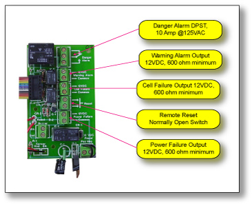
| Danger Alarm Relay One latching relay is provided for the Danger Alarm Trip Point. This relay has a maximum rating of 10A @ 125VAC. The danger relay must be manually reset by pressing the local reset button. The Danger Alarm Relay is associated with the "Danger Alarm: LED. When the alarm is energized, the relay will hold until it is manually reset using the "Reset" functions. |
|
Relay/ Output Selections: Warning - Please refer to GAS SENSORS for Warning trip points. When the trip level falls below the trip point, the output will automatically reset. No relay is provided. Output 12VDC @ 600 ohms minimum. Power Failur - Provides a 12VDC, indicating AC power is applied to the unit. No relay is provided. Output 12VDC @ 600 ohms minimum. Cell Failure - Provides a 12VDC output, indicating a signal voltage problem with the sensor. No relay is provided 12VDC @ 600 ohms minimum.
|
 |
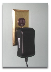
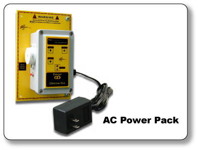
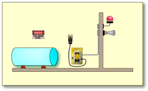
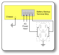
AC Power Supply Installation |
|
| Important: A battery backup system is recommeneded where AC power is likely to be interrupted. Always test the unit after a power outage or surge, however brief. |
|
 |
 |
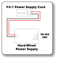
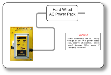
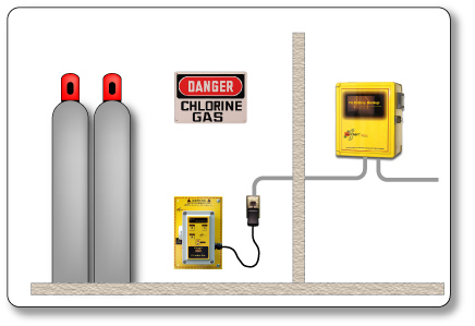
| Hard-Wired AC Power Supply The FX-1 Gas Detector can be hard wired to a fixed mounted AC power supply. A battery backup system is recommended where AC power is likely to be interruped. |
|
| Location and Mounting of Fixed mounted AC power supply. The fixed mounted AC power supply should be placed in such a way that it is easily accessible for service. Two conduit holes are provided, one at each end of the NEMA 4X enclosure. A terminal strip at each end of the fixed mounted AC power supply is provided, one for incoming 115 VAC power and the other for outgoing 24 VDC power to the FX-1. The AC power supply should be no more than 100 feet away. |
|
 |
 |
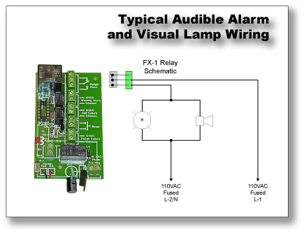
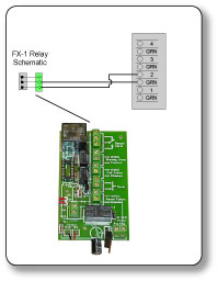
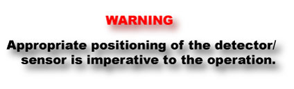
| Typical Audible Alarm and Visual Lamp Wiring Warning - Appropriate positioning of the detector/ sensor is imperative to the operation of the detector. Good positioning will give rapid alarm response to a gas leak or low oxygen level. Improper positioning can delay or prevent warning of a hazardous condition. |
|
| FX-1 Gas Detectors may not be heard or seen. The loudness of the alarm in the FX-1 Gas Detector meets (or exceeds) current standards. However, if the FX-1 Gas Detector is placed in a closed room, it may not be heard or seen by personnel, especially if the door does not have a window to see the visual alarm. Even normal noise such as traffic, motors running, radios, and air conditioners may prevent personnel from hearing the audible alarm. FX-1 Gas Detectors may not be heard or seen by persons who are hard of hearing or visually impaired. It is recommended that the remote warning device be installed to alert personnel before entering a room. Several detectors are recommended both outside the building or in any room that contain personnel, where toxic gas or low oxygen can develop. | |
 |
 |
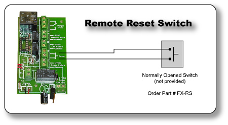
Remote Reset Switch Normally Opened Switch |
|
| A remote reset switch terminal is provided. This permits the detector to be reset from a remote location. A normally opened switch must be used. The switch is not provided, but is available optionally. | |
 |
 |
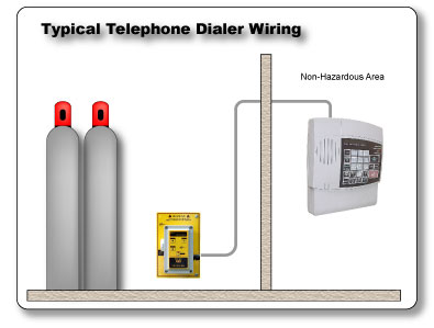
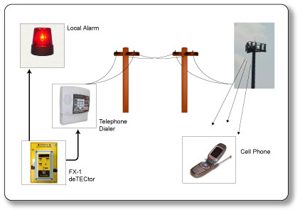
| Typical Telephone Dialer Wiring |
|
 |
|
 |
 |
| Manually Reset the FX-1 from a Remote Site Via your telephone or cell phone. | |
 |
|
 |
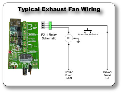
| Typical Exhaust Fan Wiring DO NOT OVER-LOAD RELAY 10 Amp maximum, @ 125VAC |
|
 |
|
 |
 |
| Important A battery backup system is recommended where AC power is likely to be interrupted. Always test the unit after a power outage or surge, however brief. |
|
 |
 |