Electrical
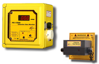
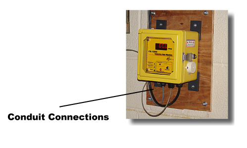
| Wiring: The FX-1500 should be wired to its own AC power source which is uninterrupted. A battery backup is recommended where AC power may be interrupted. FX-1500 Gas Detectors will not work without AC power. Four conduit holes are provided. The power supply is wired to the conduit hole on the far back right. The other conduit holes are provided for relays outputs. |
|
 |
 |
Electrical Power Supply Connection
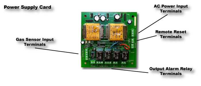
| FX-1500 Gas Detectors will not work without AC power. Use 14 gauge stranded wire only (maximum). All electrical connections are made to a terminal strip located on the power supply card. The power supply is located in the remote unit. |
|
 |
|
 |
|
AC Power Connection
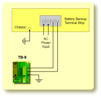
| AC Power Input Terminal TB-9 AC power input terminal is shown below. Maximum 14 gauge stranded wire only. Do not use solid wire. Always connect to an earth ground. |
|
 |
|
| All electrical connections are made to a terminal strip located on the power supply card. The power supply card is located in the remote unit. | 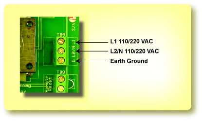 |
Auxiliary Relays
| Danger Alarm Relays Two (2) latching relays are provided for the Danger Trip Point. These relays have a maximum rating of 10A @ 125VAC. They are non-configurable and must be manually reset either by pressing the reset button or remotely. Do Not Over Load Relays 10 am Maximum, @ 125VAC Circuit Board Damage will occur if relays are over loaded. |
|
 |
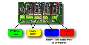 |
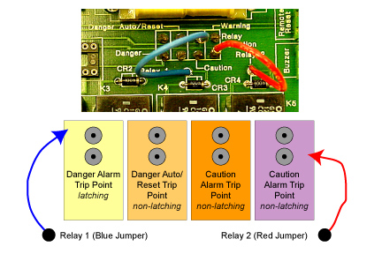
| Auxiliary Relays Two (2) auxiliary relays are provided. Relay 1 and Relay 2. They are both normally open (NO) with a maximum rating of 10A @ 125VAC. DO NOT OVER LOAD RELAYS. Each relay is user configurable to one of any four combinations. To configure the relays simply move the blue relay 1 jumper and the red relay 2 jumper to the selection required. The selections are as follows: Selections 1. DANGER - 2 points provide (latching relay, this option allows two additional latching relays or 4 total danger relays. The alarm trip points for these relays are factory set. To unlatch these relays, they must be manually reset by either locally pressing the reset button or by a user remote reset button). 2. DANGER AUTO/ RESET - 2 points provided (non-latching relay, this option allow the relay to trip at the danger alarm point. Then the concentration of toxic gas falls below the alarm trip point , the relay will automatically reset). 3. WARNING - 2 points provided (non-latching relay, this option allows the relay to trip at the warning point. When the concentration of toxic gas falls below the alarm trip point, the relay will automatically reset). 4. CAUTION - 2 points provided (non-latching relay, this option allows the relay to trip at the caution level. When the concentration of toxic gas falls below the trip level, the relay will automatically reset). |
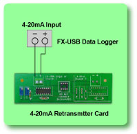
4-20mA Output
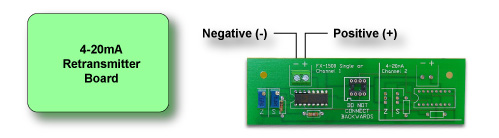
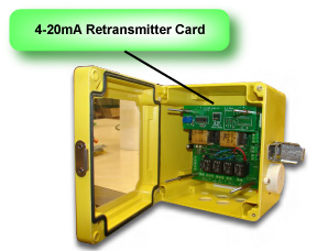
| 4-20mA Retransmitter Card (optional) The 4-20mA output signal is provided at terminal (4-20) located on the retransmitter card. This output can drive a load of up to 600 ohms. Connect the load device, matching polarity as indicated. |
|
 |
|
| Specification One- 4-20mA Output signal @600 ohm maximum load |
 |
Remote Reset Switch
 |
|
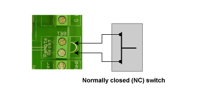
| Remote Reset A remote reset switch terminal (TB-8) is provided. this permits the Gas Detector to be reset from a remote location. A normally closed switch must be used. The normally closed switch is not provided and is optional. First, remove the jumper from the terminal and then attach the normally closed switch. Only remove the jumper when connecting a remote normally closed (NC) switch. |
 |
Auxiliary Relays
| Danger Alarm Relays Two (2) latching relays are provided for the Danger Trip Point. These relays have a maximum rating of 10A @ 125VAC. They are non-configurable and must be manually reset either by pressing the reset button or remotely. Do Not Over Load Relays 10 am Maximum, @ 125VAC Circuit Board Damage will occur if relays are over loaded. |
|
|
|
| Auxiliary Relays Two (2) auxiliary relays are provided. Relay 1 and Relay 2. They are both normally open (NO) with a maximum rating of 10A @ 125VAC. DO NOT OVER LOAD RELAYS. Each relay is user configurable to one of any four combinations. To configure the relays simply move the blue relay 1 jumper and the red relay 2 jumper to the selection required. The selections are as follows: Selections 1. DANGER - 2 points provide (latching relay, this option allows two additional latching relays or 4 total danger relays. The alarm trip points for these relays are factory set. To unlatch these relays, they must be manually reset by either locally pressing the reset button or by a user remote reset button). 2. DANGER AUTO/ RESET - 2 points provided (non-latching relay, this option allow the relay to trip at the danger alarm point. Then the concentration of toxic gas falls below the alarm trip point , the relay will automatically reset). 3. WARNING - 2 points provided (non-latching relay, this option allows the relay to trip at the warning point. When the concentration of toxic gas falls below the alarm trip point, the relay will automatically reset). 4. CAUTION - 2 points provided (non-latching relay, this option allows the relay to trip at the caution level. When the concentration of toxic gas falls below the trip level, the relay will automatically reset). |
|
 |
|
Connect a Battery Backup
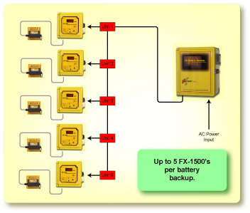
| Important A battery backup system is recommended where AC power is likely to be interrupted. Always test the unit after a power outage or surge, however brief. |
|
|
|
 |
 |
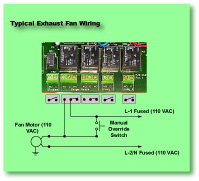
Connect a Exhaust Fan
| Typical Exhaust Fan Wiring DO NOT OVER-LOAD RELAY 10 Amp maximum, @ 125VAC |
|
 |
|
 |
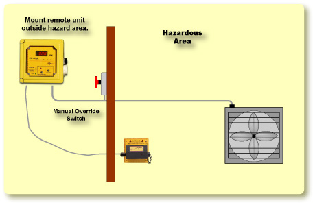 |
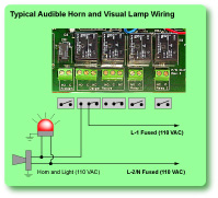
Connect a Horn and Visual Lamp
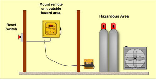
| FX-1500 Gas Detectors my not be heard or seen. The loudness of the horn in the FX-1500 Gas Detector meets (or exceeds) current standards. However, if the FX-1500 Gas Detector is placed in a closed room, it may not be seen or heard by personnel, especially if the door does not have a window to see the visual alarm. Even normal noise such as traffic, motors running, radios, and air conditioners may prevent personnel from hearing the audible alarm. FX-1500 Gas Detectors may not be heard or seen by persons who are hard of hearing or visually impaired. It is recommended that a remote warning device be installed to alert personnel before reentering a room. Several detectors are recommended both outside the building or in any room that contain personnel, where toxic gas or low oxygen levels can develop. | |
 |
 |
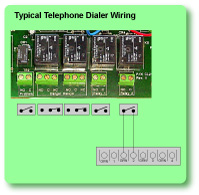
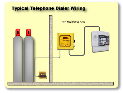
Connect a Telephone Dialer
| Typical Telephone Dialer Connection Important Configure Relay 2 to (or Relay 1) to Auto/Reset Selection |
|
 |
|
 |
 |
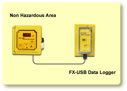
Connect a External Data Logger
| 4-20 Retranmitter Card option Required Data log events that occur during a toxic gas leak, information include date, time and level of leak. |
|
|
|
 |
 |