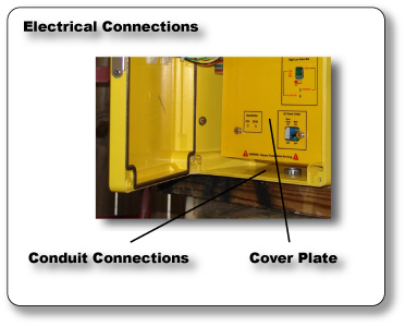
Electrical
| Conduit Holes Run all wiring to the FX-1000p in 1/2-inch, grounded metal conduit. If using only shielded cable, appropriate strain relief's or cable grips are required. Seal unused cable entry holes with appropriate plugs. Important - The electronics enclosure is not a junction box and should not have any other wiring running through it. |
|
| Important - This non-metallic enclosure does not automatically provide grounding between the conduit connections. Grounding must be provided as part of the installation. | |
| Electrical Connection Make electrical connections to terminal strips located on the bottom circuit board in the enclosure. To access this board, unfasten the retaining nuts on the four threaded standoffs, and carefully remove the cover plate and top display/ controls circuit board. Make sure that the ribbon interconnect cable remains securely attached at both ends. |
 |
AC Power
 |
|
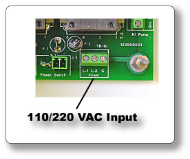
| AC Power TB-1D AC power input terminal is shown below. Use maximum 14 gauge stranded wire only. Do not use solid wire. Always connect to an earth ground |
|
| Power Requirements 100-130 VAC, 50/60 Hz. (30 watts); optional 200-240 VAC, 50/60 Hz |
 |
4-20mA Output
 |
|
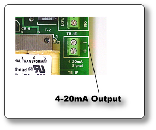
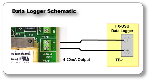
| Analog Output 4-20mA The isolated 4-20mA output signal is provided at terminal on TB-1E. this output can drive a load of up to 600 ohms. Connect the load device, matching polarity as indicated. |
|
| Analog Output One isolated 4-20mA (600 ohms max. load) |
 |
High and Low Alarm Relay Outputs
 |
|
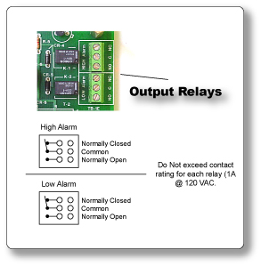
| High and Low Alarm Relay Output The FX-1000p is equipment with two electromechanical relays. Two sets of SPDT relay outputs, one for high alarm and one for low alarm, are provided on the bottom circuit board. Important - Do Not Over Load Relays, 1 amp maximum, @125VAC, Circuit board damage will occur if relays are over loaded. |
|
| Relays Two electromechanical relays (high and low alarms); SPDT (form C) contacts; rated 1A @ 120 VAC |
 |
Connecting a Recorder
 |
|
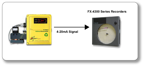
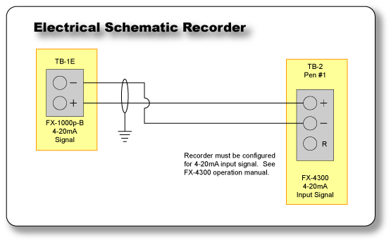
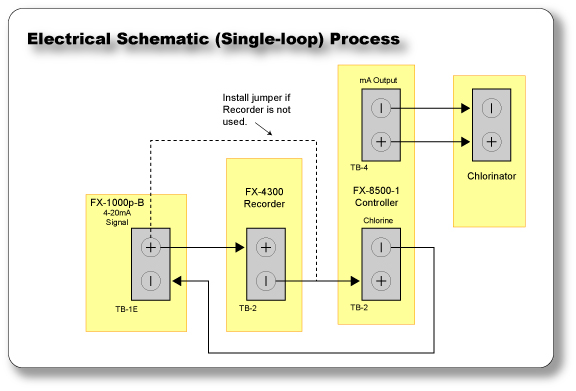
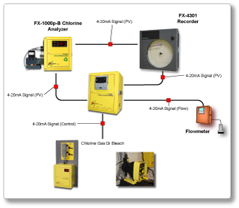
| Connecting a Chlorine Analyzer to a Chart Recorder. Recorder must be configured for 4-20mA input signal. |
|
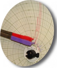
| "Recorders are Important" An often overlooked part of a chlorine system is a chart recorder. A good system will have a chart recorder tied into the residual analyzer to monitor how the system is operating. Although not quite as necessary, a second chart recorder tied into the flowmeter loop is also helpful in determining problems with chlorine residual. |
|
 |
 |
 |
|
Connecting a Telephone Dialer
 |
||
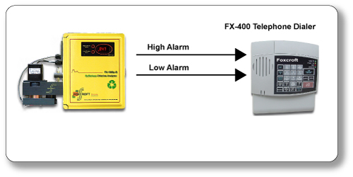
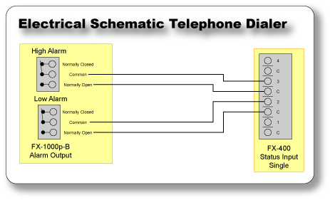
| Connecting a Telephone Dialer to a Chlorine Analyzer | ||
| The system below takes an high/ low contact from the chlorine analyzer and automatically makes phone calls to a list of several destination phone numbers until it gets an answer. When the call is answered, the unit recites the alarm condition and a full report of all monitored conditions in a synthesized voice format. | ||
 |
 |
|
 |
||
Connecting a Metering Pump
 |
|
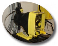
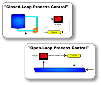
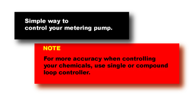
| Chlorine Residual Control In our chlorine residual control system, much of the same functionality of the car cruise control system is implemented, using different equipment specific to our process. We already know that the process we are interested in controlling is the chlorine residual level in the water. We read the chlorine residual level, or the "speed" of our process, with a chlorine analyzer. The signal from the analyzer is connected to a single or compound-loop controller, where we select our desired chlorine residual level. This would compare to the cruise control computer and speed selector push-button in the car. The output signal from the controller connects to a chlorine liquid metering pump, which varies the amount of chlorine going to the water being treated, and thus the chlorine residual. |
|
 |
 |
 |
|
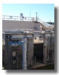
Connecting a Gas Chlorinator
 |
||
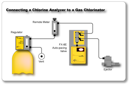
| Chlorine Gas Installation Single Loop Control Chlorine residual control system are often misunderstood and improperly implemented and as such usually ge abandoned for simpler manual or flow-paced chlorination systems. Successfully installing and running a chlorine residual control system requires a solid understanding of the system as a whole, and the role of individual components that makeup the system. |
||
 |
 |
|
 |
||
Connecting a Compound Loop Controller
 |
||
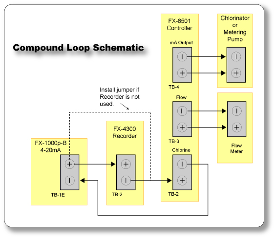
| Connecting a Compound Loop Controller to a Chlorine Analyzer The FX-8500 Compound-loop controller can provide unattended automation for chlorine residual applications. The FX-8500 Compound-loop controller provides the vital link between chlorine analyzer, flowmeter, and chlorine control device. Allows instantaneous chlorine feed changes in response to flow rate changes, and overall, time-compensated changes based on chlorine residual feedback from the chlorine analyzer. |
||
 |
 |
|
 |
||
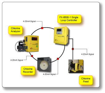
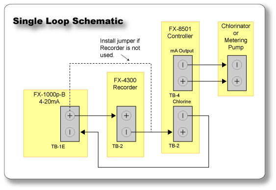
Connecting a Single Loop Controller
 |
||
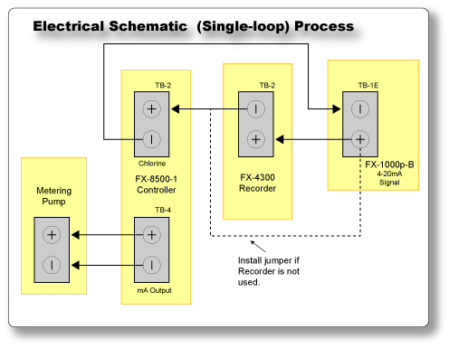
| Connecting a Single Loop Controller Provides you with unattended control, this single loop control system is the vital link between the chlorine analyzer and your metering pump or gas chlorinator. The single loop control system instantaneously changes the chlorine feed in response to a predetermine set point. |
||
 |
 |
|
 |
||
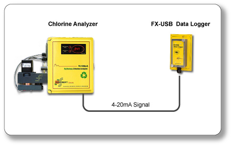
Connecting a Data Logger
| Connect a Data Logger to a existing Chlorine Analyzer • 4-20mA Current Loop Measurement Range • Logging Rates between 1s and 12 hrs. • Stores 32,000 readings • Wall Mount Enclosure |
|
 |
|
 |
 |
 |
|
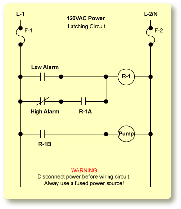
Start - Stop Operation (using High and Low Alarms)
 |
||
| Warning Do NOT exceed contact rating for each relay. Two electromechanical relays (high and low alarms); SPDT (form C) Contact Rated: 1A @120 VAC |
 |
|
| Low Alarm - K-2, Common and Normally Open - Turns metering pump "ON" when signal hits low limit. High Alarm - K-1, Common and Normally Closed - Turn metering pump "OFF" when signal hits high limit. NEVER adjust Low Alarm limit highter then High Alarm or High Alarm limit lower then Low Alarm limit. R-1 (provided by customer) DPDT Relay F-1, F-2 (provided by customer) Fuses |
||