 |
 |
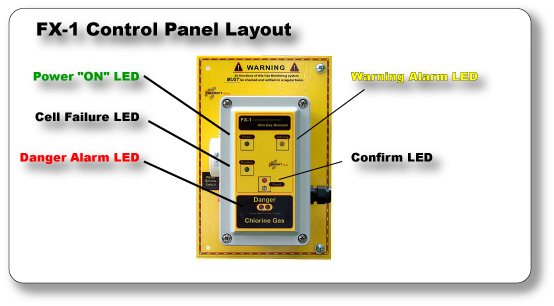
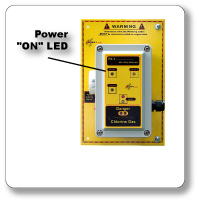
Power "ON" LED Bright Green LED Indicates AC power in turned on. Never operate the detector if the green LED power indicator is not illuminated. |
 |
 |
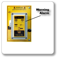
Warning Alarm LED Bright Yellow LED No Relay output. Output voltage, 12VDC @600 ohms minimum. When the concentration of toxic gas falls below the trip point level, the output will automatically reset. |
 |
 |
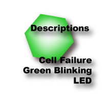 |
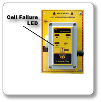
Cell Failure Green Blinking LED The cell failure alarms if the sensor voltage drops below the factory calibrated voltage (1.9VDC). Never operate the detector if the green blinking LED is illuminated. The cell failure indicating LED is not foolproof. Like all other electronic devices, the FX-1 contains many parts. Any of these parts could fail at anytime. Therefore, you must test your detector on a regular basis. Be sure to have the detector repaired or replaced when it fails to test properly. |
 |
|
 |
 |
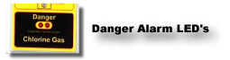
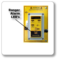
Danger Alarm 2 - Red Blinking LED's Alarm relay is latching and must be reset either by pressing the reset button or by using the Flashlight Reset Test feature. The danger alarm will not reset automatically. The Danger Alarm Relay associated with the "Danger Alarm" LED is normally a latching relay. When the alarm is energized, the relay will hold in until it is manually reset by using the "RESET" functions. |
 |
|
 |
|
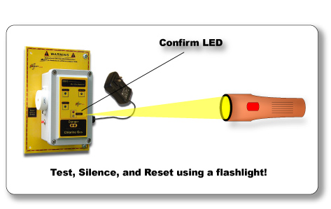
| "RESET" Flashlight Test, Silence, and Reset System The Flashlight Test, Silence, and Reset System can be used to silence the alarm buzzer, reset the danger relay, and electronically test the detector. A flashlight beam can be directed to the "RESET" portion of the control panel from as far away as 15 feet. You must stand directly in front of the detector. The flashlight must have a sufficient amount of brightness (a two D-cell flashlight with fully charged to half-charged batteries or an equivalent rechargeable flashlight) so that the beam of light can clearly be seen on the detector itself. If the flashlight's beam cannot be seen clearly, the room light must be lowered. Lower the light in the room until the beam of light can clearly be seen on the detector. A red confirm LED will appear when the Flashlight Test, Silence, and Reset System is activated. Never operate the detector if the confirm LED is illuminated and you are not activating the system. The confirm LED should only be illuminated by a flashlight. Do not install the detector in direct sunlight or light. If the "confirm" LED is illuminated, but not illuminated by a flashlight, the detector must be moved to another wall location to eliminate the light source. To avoid nuisance activation of the "confirm" light, a field adjustment can be made to correct the problem. Please contact the factory for instructions |
|
 |
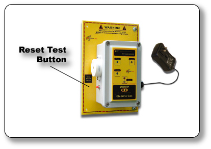
| Reset Test Button Mechanical Button The Reset Test Button is used to manually silence the alarm buzzer, reset the danger alarm relay and electronically test the detector. |
|
| Warning Never operate the detector if the "CONFIRM LED" is illuminated. All functions of this detection system must be checked and verified on a regular basis. Never create a toxic gas leak to test the functions of the detector. A certified method of testing is highly recommended. |
|
 |
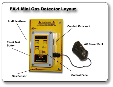
 FX-1 Mini Gas Detector
|
||||
| Foxcroft Equipment and Service Company, Incorporated 2101 Creek Road - Glenmoore, PA 19343 - USA 1.800.874.0590 - 1.610.942.2888 - FAX 1.610.942.2769 Email: sales@foxcroft.com All Rights Reserved - All material contained in this Web Site is copyrighted - No material or ideas contained within this Web Site shall be used or copied without written consent from Foxcroft. ©2009 RWI3rd |
||||